
Categories
Recent Posts
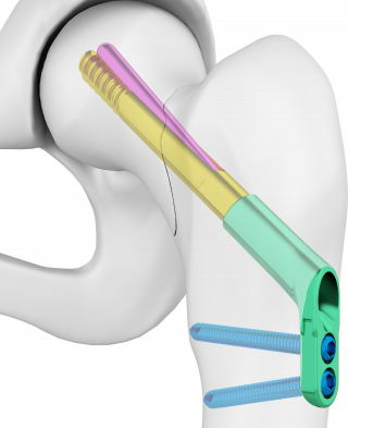
Double Medical CCS VS. Depuy Synthes FNS
|
|
CCS |
FNS |
|
Lag Screw |
Thread design: φ10.5 |
Polished design: φ10 |
|
Antirotation Screw |
Polished design: φ 6.0 |
Thread design: φ6.5 |
|
Divergence Angle |
5° |
7° |
|
Postoperative Sliding compressure Distance |
15mm |
20mm |
|
Locking Screw |
15°Fixation |
Parallel Fixation |
|
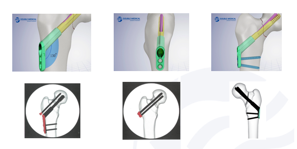
Collodiaphyseal Angle |
130° |
130° |
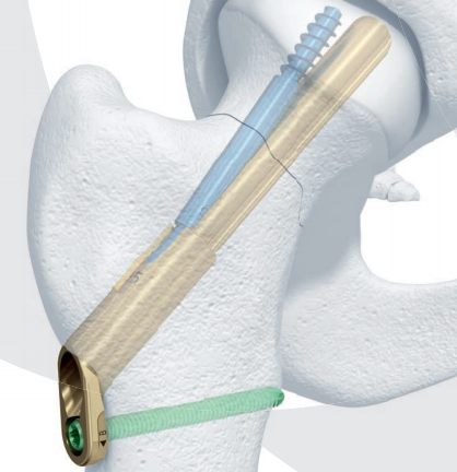
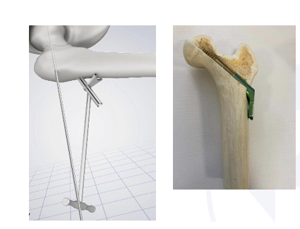
CCS Lag Screw
Tapered thread design of CCS Lag Screw which is different from the parallel thread design of DHS. The tapered thread can better compact surrounding cancellous bone, and achieve good anchoring.
Take Sawbones’ Artificial bone as the object with a density of 20 pcf,drill holes on the bone, then screw the threaded part of CCS, DHS and 7.3mm Cannulated Screw completely into the bone, and then remove them at a rate of 5mm/min, and record the maximum force value.
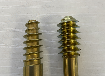
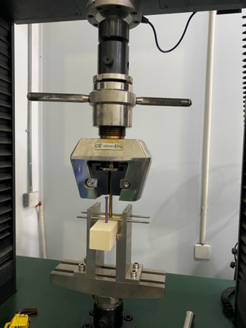
Experimental results: The 7.3mm Cannulated Screw was pulled out at 1120N, the DHS Lag Screw was pulled out at 1250N, and the CCS Lag Screw was pulled out at 1667N.
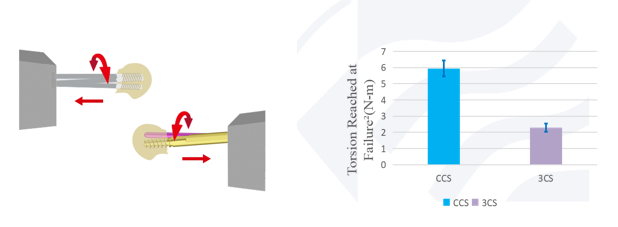
Conclusion: The pullout force of CCS Lag Screws is better than that of DHS Lag Screws, and better than 7.3mm Cannulated Screw
Take Sawbones’ Artificial bone model as the object, use a pendulum saw to artificially make a fracture model, fixing with CCS ang CS according to the procedure, and then apply a torsion force to the specimen model at a certain rate until the model fails, and record the torsion reached at failure.
Fixation Plate:
Controllable Active Compression Intraoperatively, and 15mm Sliding Compression Distance Postoperatively
1. No active compression intraoperatively, provide 15mm sliding compression distance postoperatively.
2. Allow 10mm compression distance intraoperatively, and provide 15mm
sliding compression distance postoperatively.
As long as follow the procedures, there will be a sliding compression distance of 15mm. But for Synthes’ FNS, if perform actively compression during the operation, the 20mm postoperative sliding compression distance will be failure.
Unique indicator shaft and rotary knob design to ensure controllable compression
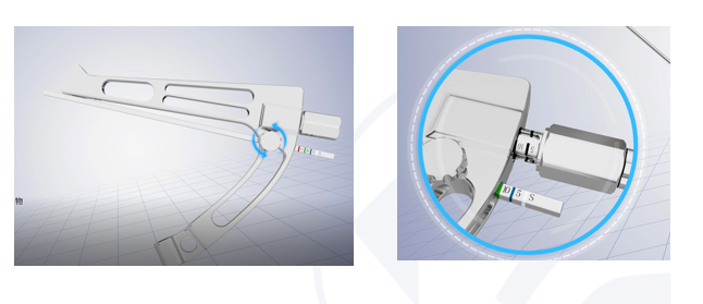
CCS Insertion Handle
1. The design simplifies the surgical operation, a Guide Wire can be insert to the Insertion Handle, which effectively prevent reduction loss during the insertion.
2. Insertions of Fixation Plate, Lag Screw, Antirotation Screw, Locking Screw are all completed on the Insertion Handle, no need to change the instrument during the operation
CCS Guide
The design of 130°CCD angle highly fits to bones. Use the Guide when inserting the Guide Wire, otherwise it will be difficult for the fixation plate to fit the bone surface.
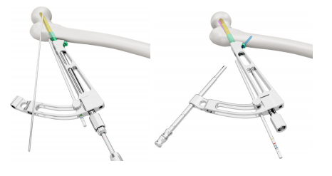
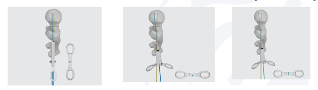
CCS Correction Guide
Femoral neck surgery often requires fine-tuning of the Guide Wire, which is inconvenient with bare hands.
The Correction Guide provides easier operation.
Three Types of Adjustments
Ⅰ. Parallel correction with new entry point anterior (5mm).
Insert the Correction Guide into the initial wire (blue) and turn the Correction Guide to locate the new entry point. Then use a new guide wire in the parallel hole (yellow) and remove the original guide wire.
Ⅱ. Angle correction towards anterior (5°) with new entry point superior (5mm).
Insert the Correction Guide into the initial wire (blue) and turn the Correction Guide to locate the new entry point. Then use a new guide wire in the 5° hole (yellow) on the left or right.
https://www.doublemedicalgp.com/compound-compression-system-ccs_p203.html
Please read on, stay posted, subscribe, and we welcome you to tell us what you think.


 Tel : 86 592 6087101
 Email : info@double-medical.com