
Explanation of TINA Universal 5.5 System
Feature of implants
Pedicle Screw:
Ultra-low profile, reduce irritation
Stronger fixation:
Two-step locking nut:
Transconnector:
TINA 5.5 Transconnector I:
TINA 5.5 Transconnector II:
Surgical Technique:
Instruments set:
Instrument Features:
TINA System Instrument Set (upgraded) equipped with various of instruments with unique design and excellent performance.
Surgical procedure:
1. Patient position:
The patient is placed in the prone position with longitudinal incision centering in posterior thoracic-lumbar. Expose spinous process, lamina and lateral segments of the joint that require fusion. The part of the lower articular process was excised to improve the surgical field, so as to improve the rate of bone grafting and fusion. The lower articular process of 3-5mm was excised, and the articular cartilage of the upper articular process was exposed, so as to locate the pedicle screw insertion point during the operation.
2. Entry Point:
The entry point varies with the structure of the posterior part of the spine. During the operation, the entry point can be determined by observing transverse process, the lateral wall of the transverse pedicle isthmus and the base of the superior articular process.It is helpful to memorize superior articular process principle (A) and the inner/outer and head/end entry points (B).

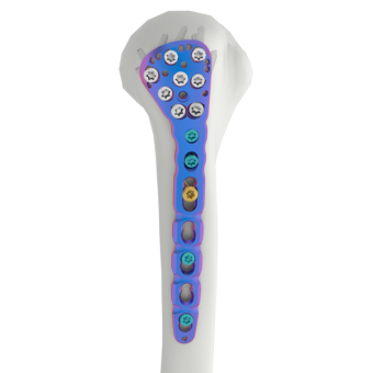
As shown in the picture, the blue marking points can be used for direct access by screws with fixed angle or screws with variable angle, while the green marking points can only be used by screws with variable angle, according to anatomical characteristics.

3. Establish Pedicle Channel: Open cortex with pedicle awl. Further open pedicle with pedicle probe.
4. Probe the Pedicle Channel: Use the soft or hard feeler for screw channel to probe the pedicle screw channel, checking the wall for perforations. The depth could be checked by the marking on the feeler.
5. Check the Position/Tap to Cortex: Place the fixation pin (left and right) into the pedicle channel by insertion device. Confirm the angle and depth under the image intensifier. Choose the appropriate tap which to tap and check the pedicle path with pedicle probe once again.
Attention: we usually recommend the diameter of tap is 1mm smaller than the final screw. If pedicle is extremely weak or slender, considering equal diameter tap.
6. Screw Insertion: Squeeze the knob to adjust the screwdriver positions forward or backward to achieve the switch of Short Arm Pedicle Screw Screwdriver and Long Arm Pedicle Screw Screwdriver. Use the screw alignment handle to rotate and align the screw heads.
7. Rod Bending and Placement: Use trial rod to determine the shape and length of the rod. Bend the rod by bending pliers according to the pre-bending arc. Rod is placed into the top-loading pedicle screws by using holding forceps. Use the rod pusher or rocker fork to simplify the process. Bending irons can be used for further contouring after rod insertion.
8. Nut insertion and Temporary Tightening
a. One-step nut insertion: Insert the tip of the holding screwdriver for one-step nut into the one-step nut. Then, insert the nut through the correction sleeve, lastly, thread the nut clockwise into the screw head for temporary locking.
b. Two-step nut insertion: Insert the tip of the screwdriver shaft for the two-step outer nut into the two-step nut. Then, insert the nut through the correction sleeve. Thread the outer nut clockwise into the screw head for temporary locking. Lastly, attach the screwdriver shaft for the two-step outer nut to the 10N.m torque indicating handle and final tighten the outer nut through counter torque sleeve
Use the screwdriver shaft for inner nut to temporary tighten the inner nut.
10. Reduction: Once reduction has been achieved, the ratchet handle will remain in the reduced position. Keep the reduction forceps in the closed position until the nut is attached to the screw. To remove the reduction forceps from the screw, ensure the ratchet handle is fully open. Hold the lower part of the reduction forceps with one hand and press it against the screw head so that one tip disengages from the screw head. Then, carefully tilt the reduction forceps downward.
11. Distraction or Compression: If either compression or distraction is needed, in either maneuver, the nut on one side of the motion segment should be provisionally loosed by disassemble wrench for two-step outer nut and disassemble screwdriver shaft for two-step inner nut. The correction sleeve could secure the rod and implant construct and at the same time be performed to distract or compress. Once satisfactory compression or distraction has been achieved, final tightening trough correction sleeve could be taken.
12 Final Tighten:
a. Final Tighten One-step Nut: Assemble the screwdriver shaft for one-step nut with the 10N.m torque indicating handle. Place the counter torque sleeve over the screw head. Make sure the screwdriver is completely inserted and turn until the torque indicating handle clicks.
b. Final Tighten Two-step Nut: Assemble the screwdriver shaft for two-step inner nut with 10N.m torque indicating handle. Insert the screwdriver shaft through the rod pusher / counter torque. Make sure the screwdriver is completely inserted and turn until the torque limiting handle clicks.
13. Tab Removal: Remove the extended tab by tab remover.
14. Transconnector Assembling: Select the appropriate transconnector. Then, loose the transconnector fixation screw to the point of resistance. Lastly, place the transconnector on the rod by holding forceps for transconnector.
Please read on, stay posted, subscribe, and we welcome you to tell us what you think.


 Tel : 86 592 6087101
 Email : info@double-medical.com